 |
||
| Documentation | Software | F.A.Q. | Spectrum mode | | ||
The architecture of the computer Sprinter.Introduction.The brief description of the computer Sprinter. Realization. Loading the configurations. Configurations description. Allocation of Sprinter RAM. Video part of RAM and address modes of video RAM. Allocation of video RAM. Structure and modes of a screen. Palette. Introduction The personal computer Sprinter is a multiform computer with 8 bit processor Z80 by Zilog� Inc. The ALTERA� PLD is most important part of the computer. Today computer Sprinter use the board Sp2000 as the mainboard. The mainboard Sp2000 was designed at the end of 2000 specially for support of the future models of the computer and has a some features, which the description in this manual too. In the beginning we will explain the main concepts which one to you will meet in this manual. Model of the computer - are the configurations in the ROM. It determining features and possibility for the user. The modern model of the computer Sprinter is alone and it has this name too. The computer configuration - position of logical components in PLD. The main configuration - active configuration after power on of the computer and include most relevant and frequently used modes of the computer model. Configuration mode - change of the characteristics of activity of the computer in the current configuration. The Fast RAM - RAM, where the processor can work on a high frequency without waiting. The physical memory unit - 16K unit of a base memory of the computer. We use the hex number for it - #00..#FF The logical memory unit - 16K the Spectrum memory scheme unit. We use decimal number - 0..15 The brief description of the computer Sprinter. CPU Z84C15 (21MHz/3.5MHz)
RAM 4Mb (64Mb)
Fast RAM 64Kb
ROM 256Kb
Video RAM 256Kb (512Kb)
FDD controller WD1793
Support FDD: 3,5" disk (1.44Mb/720Kb)
5,25" disk (720Kb)
Real time clock, CMOS DALLAS
HDD controller IDE/AT
Keyboard controler 101key/AT
Mouse controller MS-Mouse
Slots ISA-8
Audio out AY-3-8910 (in PLD), Stereo 8 bit (16 bit)
Video out TV, CGA analog monitor, RGB
Graphic mode 320x256x256, 640x256x16, Spectrum standard screen
Text mode 80x32x16
Realization. CPU Z84C15 and ALTERA PLD EP1K30QC208-3 are core of computer Sprinter. Another components: ROM; slot for 72 pin SIMM; video RAM; 64Kb Fast RAM; FDD controller (WD1793); buffers for joystick, tape, printer, keyboard, FDD, HDD and mouse; ISA 8 bit; ALTERA PLD EPM7064SLC100-10. This PLD don't change it's configuration and Sprinter use it for synchronization and start of computer. And Sprinter mainboard has place for real time clock. Except for peripherals and buffers there are chips of decoding, the inputs which one are connect to the CPU through PLD. It allows easily to change addressing of devices, without any roads change of mainboard. When computer starting and after reboot of the computer PLD load data from ROM. It allows to change the data in PLD in a burn-time of the computer. The computer has the flex architecture, in which one the changes in its many parts are possible. For example, it is impossible to say about particular addresses of peripherals ports, as they can be changed by reprogramming PLD and data in the RAM which one determines the configuration of ports. The real addresses you can use only in the real configurations, for example, in the Spectrum configuration.
Loading the configurations. At power on and after press Reset button all data in PLD has been cleared. PLD is waiting for loading data. CPU is disconnected from any peripherals. The ROM or Fast RAM is included in its address space of memory. Any writes to address space of CPU memory in this moment will writing to PLD. The program in connected page of a ROM save the data of the configuration in to the PLD. In this page of a ROM there are data of the main configuration. The program of a configuration loading check the flag in the Fast RAM and, if it is found - load the data from the Fast RAM in to the PLD. If the flag is is not found - load the data from the ROM. This is a foundation of Sprinter reconfiguration. The internal information of a data block PLD is the closed information of ALTERA Corp. This corporation tenders also software for creating the schemes inside PLD. The creating of the new configurations can is made only at the computer, for which one is created the programs of creating of the schemes in PLD - MAX-Plus II. The version of this program for the computer Sprinter does not exist. Configurations description. Two configurations are included in modern model of the computer Sprinter. Sprinter configuration. This is main configuration of Sprinter. Includes a memory allocation up to 4Mb, graphic screen with modes 230�256 pixels (256 colors) and 640�256 pixels (16 colors). The modes use pallet with 16M colors. Also configuration includes a text mode 80�32 characters (16 colors). Included the controller of FDD, controller IDE, AT keyboard controller (built on an internal serial port of the processor), Accelerator, support sound DAC in 8 bits mono. The Accelerator will be used for operations with RAM and videoRAM, accelerates operations of transfer data blocks and filling the RAM of one byte up to a physical speed limit of the RAM. As allows to speed up logical processing of data blocks on functions AND, OR, XOR. Spectrum configuration. This configuration was created for possibility of using software created for the computer ZX Spectrum and its some clones. The configuration has a capability to work in several modes. There is a musical coprocessor AY-3-8910 at all modes. Sprinter ZX mode. This is a intermediate mode for access to Sprinter capabilities in Spectrum mode. Such solution allows to extend capabilities Spectrum programs without hard change of the code.
This mode used for 100 % compatibility with original model ZX Spectrum (ULA, screen sync, ets.). Pentagon 128 mode Most popular Russian Spectrum clone with 128Kb RAM.
Russian Spectrum clone with 256Kb RAM.
Russian Spectrum clone with 512Kb RAM.
The allocation of Sprinter RAM is double level. The RAM of the computer (4Mb) is parted into units on 16Kb, assigned by one-byte number. The address space of the processor Z80 is parted into 4 windows with addresses #0000..#3FFF, #4000..#7FFF, #8000..#BFFF And #C000..#FFFF, which call as windows with numbers 0, 1, 2 and 3. The ROM and Fast RAM is parted on 16Kb units also. Physical number of page of a ROM has values #E0..#EF, and Fast RAM - #F0..#FF. Now for addressing of the Fast RAM will be used only 2 and 1 bits from this number. Stayed 3 ports of pages of memory remain at present in a reserve.
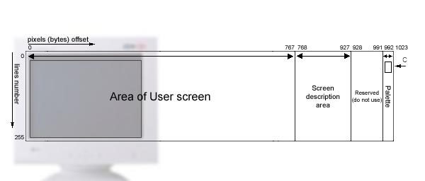
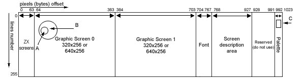
The scheme of a memory allocation allows to connect in address space of the processor not only RAM or ROM, but also ports, and memory ISA of cards pasted into the slot. At connect in addresses #C000..#FFFF through port #1FFD expanded RAM pages, on their place it is possible to readdress slots. You can write to port of one of these pages value applicable to the ISA-slot, to which need to make the reference. This value as indicates, to what the reference is conducted, to ports or memory of the slot (info about numbers will be lower). After connected the Spectrum configuration memory units are connect to logical units Spectrum scheme of a memory allocation. In each window of the processor the logical memory unit places agrees Spectrum allocation. In a window 0 the ROM, in a window 1 - page 5, in a window 2 - page 2, in a window 3 any of pages 0 is connected.. 7 for Pentagon-128 mode, 0.. 15 for Scorpion-256 mode and 0.. 31 for Pentagon-512 mode. In Scorpion-256 mode instead of a ROM the logical page with number 0 can be connected. Each logical unit has own physical number of RAM page, connected in it. The logical pages with numbers 0, 2 and 5 have dual numbers, first for static connected in windows 0, 1, 2 of processor, second for connect in window 3. The numbers of physical pages placed in these units, are coincide in a Spectrum mode. In the Spectrum configuration each page of ROM or RAM has the port, in which one physical number of page is placed. 32 ports of memory pages total (in Pentagon-512 mode 16 ports are added). 16 ports used for numbers of RAM pages connected in the third window of the processor. Three ports used for connect RAM pages in windows 0.. 2. One ports will be used for connect of different ROM pages. One port - for connect of Fast RAM page instead of a ROM. And one port is a port of system page connected on a place of a ROM at once after computer reset with keys Ctrl+Alt+Del. Video part of RAM and address modes of video RAM. The data can be written to Video RAM with use two address modes. The first address mode used for graphic and text in the Sprinter configuration. The second mode used for character generators in text mode in the Sprinter configuration and for graphic and text in the Spectrum configuration. Video part of RAM and video RAM are different. Video part of RAM include copy of screen. But this copy and screen may be different if you wont. 256Kb of Video part of RAM use pages #50..#5F. At set up of these pages in any CPU window and at the call to addresses of this window the address multiplexer is toggled in a first address mode. In this mode bits 3..0 of page number do not correct memory address. It call special mode. In first mode the address of memory will be took from number by RGADR and ten low bits of CPU address. In second mode video part of RAM place in #4000..#5FFF or #C000..#DFFF for logical memory unit 5 and 7. Any physical memory unit (except #50..#5F) can be video part of RAM after set to this addresses of CPU. Sprinter hasn't static video RAM page. You can use any RAM page as video RAM page. Allocation of video RAM. The video RAM of Sprinter is shaded memory. When the date put into the video RAM, this date put into the RAM too. When you need to read a video data, the information is read from video part RAM, and the video of the RAM is no accessible. But nonaccessibility of a video RAM is not principled limitation. It is feature of modern configurations. The allocation of video RAM is partially static and partially programmatic. The static part of allocation determines where there are data of video mode and the data of a graphic pallet. Programmatic part of allocation determines, where there are data graphic, text and Spectrum modes of a screen, opened by functions BIOS. The modern model of computer Sprinter has 256K video RAM. Video RAM include information like to large video screen of 1024x256 bytes. This large video-screen parting to some areas. The frontieres of areas has numbers of bytes from first line with 1024 bytes long (#0000..#03FF). For example, the date of palette placed at #03E0.. #03FF for first colour. For next colour you need add 1024.
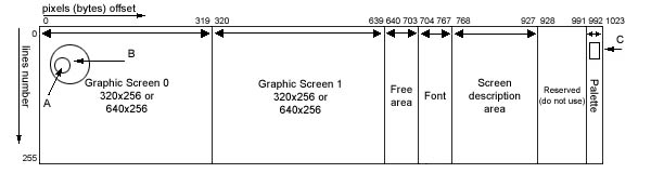
The first graphic screen - #0000..#013F The second graphic screen - #0140..#027F Font - #02C0..#02FF Screen description area - #0300..#039F. The area #03A0..#03DF is reserved. The graphic palettes - #03E0..#03FF. When you use BIOS functions in Spectrum configuration the data of graphic and Spectrum screens place in addresses #0000..#02FF.
Spectrum screens - #0000..#003F The first graphic screen - #0040..#017F The second graphic screen - #0180..#02BF Font - #02C0..#02FF Screen description area - #0300..#039F. The area #03A0..#03DF is reserved. The graphic palettes - #03E0..#03FF.
|